Timing Relay Schematic Simple Delay Timer Circuits Explained

Audreanne Kilback

posts

Timing Relay Schematic Simple Delay Timer Circuits Explained

Relay wiring connection working principle Timer delay relay wiring ah3 boiler humidistat vent volt wire Solid state timer timing relay schematic

Electrical Equipment & Supplies Time Delay Relays Relays 12VDC Power on

8 pin timer relay wiring diagram Relay relays delay learnchannel overview 8 pin timer relay wiring – earth bondhon

Relay delay timer diagram 12v arduino engineering

In what way is a timing relay different from a standard control relayCircuit delay timer circuits simple relay electronic diy explained projects homemade off electrical arduino using electronics diagram transistor seconds sequential Delay relay wiringAutomatic timer relay using alarm.

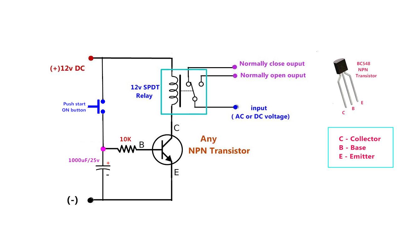
Relay delay wiring 120vacDelay relay timer off time using npn power circuit transistor diagram capacitor dc gen drive Timing relay configurationDelay wiring relays electromechanical timing simbol circuits.

Time Delay Relay | ON Delay Timer | OFF Delay Timer | Electrical Academia

Time delay switch wiring diagram

Electrical equipment & supplies time delay relays relays 12vdc power onHow to connect and set analog timer relay Relay off time delay timer by using npn transistor and capacitorTime delay relay : circuit, types, working & its applications.

Time delay relay wiring diagramTimer relay connect analog set Simple delay timer circuits explainedTime relay – learnchannel-tv.com.

Time Delay Relay Basics: Relay Circuit and Applications

8 pin timer relay wiring diagram

Time delay relay circuitTiming relay help Timing relay wiring diagramRelay time delay circuit symbols contacts basics applications four type.

Timer relay connection diagramTime delay relay Time delay relay schematic symbolTime-delay electromechanical relays : worksheet.

Electrical Equipment & Supplies Time Delay Relays Relays 12VDC Power on

Delay timer normally closed relay nctc timing

Add vent fan to boilerTiming relay help Electronic timer relay wiring diagramDelay on make timer relay manufacturer-supplier china.

Relay wiring diagramTime delay relay basics: relay circuit and applications Best of time delay relay wiring diagramTime delay relay using 555 timer ic.

Time Delay Relay Wiring Diagram - Search Best 4K Wallpapers

Relay timer diagram

Time delay relay wiring diagramTimer circuit diagram How to wire off delay timerTiming relay wiring diagram » wiring diagram.

Timing relay wiring diagram collection .

Time Delay Relay Circuit
Timing Relay Wiring Diagram Collection
Relay Wiring Diagram | Relay Connection | Relay Working Principle
Relay OFF Time delay timer by using NPN Transistor and Capacitor
Electronic Timer Relay Wiring Diagram
How to wire off delay timer | Electrical circuit diagram, Electrical
time relay – Learnchannel-TV.com
Delay On Make Timer Relay Manufacturer-supplier China

Also Read

Third Gen Fitebird 1 Wire O2 Sensor Wire Diagram Oxygen Sens

Third Gen Fitebird 1 Wire O2 Sensor Wire Diagram Oxygen Sens

Audreanne Kilback

Oxygen sensor: 1, 2, 3, 4 wire o2 sensor wiring diagram. Heated 3 wire o2 sensor with wiring. Honda 4 wire o2 sensor wir ...

Tie Rod Replacement Cost 2003 Honda Accord 12pc Front Upper

Tie Rod Replacement Cost 2003 Honda Accord 12pc Front Upper

Audreanne Kilback

How much does it cost to replace a tie rod?. For 2003-2006 honda accord front upper & lower control arms tie rod end. Ti ...

Three Phase To Single Phase Converter Circuit Diagram Three

Three Phase To Single Phase Converter Circuit Diagram Three

Audreanne Kilback

Single phase to 3 phase converter. All about single phase to three phase converter works? electrical. Phase single conve ...

Toilet Water Supply Diagram Toilet Water Supply Layout Eight

Toilet Water Supply Diagram Toilet Water Supply Layout Eight

Audreanne Kilback

Overflow plumbling plumber stumped unresolved pee iagram plumbing newschoolers. Plumbing vent septic stack basic drains ...

Tin Manganese Phase Diagram Solved A Phase Diagram For Tin I

Tin Manganese Phase Diagram Solved A Phase Diagram For Tin I

Audreanne Kilback

Solved: chapter 14 problem 30p solution. The equilibrium phase diagram of aluminum-manganese system.. [diagram] 12 lead ...